We have built our simulator with some universal quantum gates: $P(\theta)$, H, and CNOT.
These gates have the property that:
You can build any unitary using these gates.
They aren't especially bad. What we mean by this is that there isn't another set of reasonable gates that are much better. One way to see this is that we can build other reasonable gate sets from this set without too much trouble.
They aren't cheating. A couple special 1 and 2 qubit gates are reasonable atomic constructs that experimentalists can build. There are lots of other choices but we will see (later) that with different choices you can quickly build up this set (and then can build anything).
We will focus on showing the first two bullet points in this section. We will first show how to reasonably efficiently build any one and two qubit gates. This will tell us that there isn't much penalty for using the set we've chosen. Then we will also see how to build any arbitrary unitary from these gates.
To accomplish this, what we will need to do is figure out how to take an arbitrary unitary and break it up into H, P, and CNOT.
As our first step we are going to figure out how to build arbitrary 1 bit unitaries.
Next, we will generate arbitrary control-unitaries (first one bit, and then otherwise)
Finally, we will put it all together to generate an arbitrary unitary. It is important to note that this algorithm will eat an arbitrary unitary and give you a circuit but there's no reason to think that the circuit you get out will be the most efficient way of doing things.
If you're goal is just to make it through Shor's algorithm, then you only need to implement a small subset of these gates. To get through Shor you are going to need
Control-Phase: To make this gate do, NOT -> Rz -> Control-Rz -> Control-Phase
Control-Classical Function: This will be done on a separate page.
Swap: Figure out how to build a swap using three CNOT
Long-range CNOT: (possibly already implemented in your simulator but you can also do long-range CNOT by swapping up and then CNOT and then swapping down)
Ideally you want to figure out how to do all these things using H, P, CNOT. You could avoid this, though, by just implementing these atomically in your simulator.
We are going to spend a bit of time building circuits for more sophistcated gates. We are going to start by building 1-wire circuits. When you just have 1-wire (and therefore 1-qubit) we can visualize that qubit on a bloch sphere (see here). This is sensible because a single qubit has three parameters that specify it (two complex numbers and on constraints). In our language, $|0\rangle$ points in the $\hat{z}$ direction, and $|1\rangle$ points in the $-\hat{z}$ direction. $|0\rangle + |1\rangle$ is in the $\hat{x}$ direction.
We can graph a single qubit in python using the following:
1 2 3 4 5 6 7 8 9 10 | |
Go ahead and graph a couple vectors and see what it does. Also, try to figure out what the Hadamard gate does.
Suppose you want a gate that does $|0\rangle \rightarrow |1\rangle$ and $|1\rangle \rightarrow |0\rangle$.
Figure out how to build a circuit from Hadamard and phase gates which does this. Think about what this does on the Bloch sphere (or just graph it on some vectors before and after)
The three pauli gates are
\[Z= \begin{bmatrix} 1 & 0 \\ 0 & -1 \\ \end{bmatrix} \]
\[X= \begin{bmatrix} 0 & 1 \\ 1 & 0 \\ \end{bmatrix} \]
\[Y= \begin{bmatrix} 0 & -i \\ i & 0 \\ \end{bmatrix} \]
Figure out how to build these circuits from Hadamard and phase gates. Think about what this does on the Bloch sphere (or just graph it on some vectors before and after) Notice that X=NOT.
Often we want to take a qubit and do a rotation around these axis.
$$R_x(\theta)=e^{-i \frac{\theta}{2} X}$$
$$R_y(\theta)=e^{-i \frac{\theta}{2} Y}$$
$$R_z(\theta)=e^{-i \frac{\theta}{2} Z}$$
Build a python code which eats $\theta$ and produces circuits for these three gates.
Here we will consider how to generate arbitrary one-wire unitaries given our univesal gate sets. Notice that a one-wire unitary essentially is a rotation of the Bloch sphere and so we expect to be able to write it as rotations.
A unitary matrix has the property that $UU^\dagger=I$. It then follows that $\det(UU^\dagger)=1$ which implies $\det(U)\det(U^\dagger)=aa^*=1$. Therefore the determinant of a unitary matrix, $\det(U)=e^{i\phi}$.
We will find it convenient to write unitaries as
\[ U=
\begin{bmatrix}
a_{11} & a_{12} \\
a_{21} & a_{22}
\end{bmatrix} =
e^{i\phi/2} \begin{bmatrix}
u_{11} & u_{12} \\
u_{21} & u_{22} \\
\end{bmatrix} =e^{i\phi/2}
\begin{bmatrix}
e^{i\phi_1}\cos(\theta) & e^{i\phi_2} \sin(\theta) \\
-e^{-i\phi_2}\sin(\theta) & e^{-i\phi_1} \cos(\theta) \\
\end{bmatrix}
\]
with certain constraints on these values.
If we then let
$$\alpha = arg(u_{11})-arg(u_{21})$$
$$\beta = arg(u_{11})+arg(u_{21})$$
$$\theta = \arctan(|u_{21}|/|u_{11}|)$$
we can write
$$U = e^{i\phi/2} R_z(-\alpha)R_y(2 \theta)R_z(-\beta)$$
(At the moment you don't have to worry about the global phase out front because it just gives a global phase to the entire system. - You should understand this!)
Convince yourself that this gives you the right matrix. This also checks that my formulas don't have missing factors of two or minus signs somewhere (one way to convince yourself is to write three lines of code to take a random unitary, split it up like this and multiply out the matrices to check ).
Build a python code which eats the unitary matrix and produces a one-wire circuit for $U$.
For testing you probably want to generate random unitaries and see if it does the correct thing. To get a random unitary, generate a random matrix, make it Hermitian, multiply it by $i$ and then exponentiate it using scipy.linalg.expm.
Verify that when you run your one-wire circuit through your simulator that you get the correct results.
Here we are going to start learning a bit about the power and the limitations of quantum computing. First let's think about simulations where you only have one-qubit gates.
Do the following test. Choose some random unitary matrices with determinant 1. Run your circuit and get the quantum state as output.
1 2 3 4 | |
Now, run three simulations
1 2 | |
and
1 2 | |
and
1 2 | |
get your output and tensor product your outputs. Compare it to the output you got when you had three wires? What do you notice? Why is this?
Now, suppose that these four circuit descriptions have
1 | |
at the end. Can you figure out the relationship of the probabilities of the first circuit description compares to the last three? In other words, can you write some python code that takes a circuit description with only single qubit gates and simulates it exponentially faster then your general quantum simulator. You don't have to do this for a grade but it's a nice illustrative project if you're ahead.
Go ahead and write some code for preprocessing a circuit description that takes circuit elements such as X,Y,Z,Rx,Ry,Rz,U and produces a new circuit description that involves only H, P.
In a moment we are going to do a general Control-U but let's warm up with just a Control - Rz.
First, figure out how to make a Rz using Not, P(theta) and P(-theta) (possibly with factors of 1/2). Then, notice that if you don't have the Not's in there that you get the identity.
Then figure out how to use this fact to build a control-Rz
Your control-Rz and control-phase should differ by a global phase if the control bit is 1. Figure out how to do modify your control - Rz to do this.
Show that
accomplishes this, write down the circuit description and run it in your simulator.
\[V=
\begin{bmatrix}
1 & 0 \\
0 & i
\end{bmatrix}
\]
(how do you get this matrix from the universal circuit element). Build a circuit description and run it through your simulation and see that it works. Then add it to your preprocessor using
1 | |
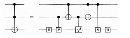
where the first two numbers are the wires for the control and the last wire is the wire for the not. Tofelli circuits are universal for (reversible) classical computing. This means that any classical function you have can be written with just tofelli (and anything written with just tofelli can be simulated classically - do you understand why?).
We've seen that we can generate any 1-qubit unitary matrix. Now we'd like to see how we can generate ctrl-U for one-wire U. Figure out how to do a ctrl-U. Here you have to pay attention to the phase $e^{i\phi}$ since if it's controlled it only applies to some of the binary numbers.
You might want to use the fact that
$A=R_z(\alpha)R_y(-\theta)$
$B=R_y(\theta)R_z(-\frac{\beta+\alpha}{2})$
$C=R_z(\frac{\beta-\alpha}{2})$
and that $ABC=I$ and $AXBXC=U$ (and that X=NOT) (check this to feret out any factors of 2 I have wrong).
Add this to your preprocessor using the syntax
1 | |
where the first number is the control and the second number is the wire the unitary is on.
Once you've figure out how to do ctrl-U for one wire, figure out how to do a ctrl-U for many wires. Write some code that takes a $U$ written out as circuit and a control-wire and spits out the description of ctrl-U on many wires. If you're feeling ambitious you can come up with some syntax to do this but you don't need to.
[ ] Graded: Convince us that your preprocessor works correctly for all the gates up to this point.
You don't need to do this for credit but think about how you would do this
This is just for fun and is not part of anything graded. But if you're way ahead this is a nice challenge
Figure out how to take an arbitrary unitary written as a big matrix and write code which generates the circuit description for this unitary.
Here there wants to be a discussion with using discrete gates to generate our universal gates.